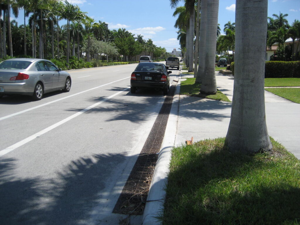
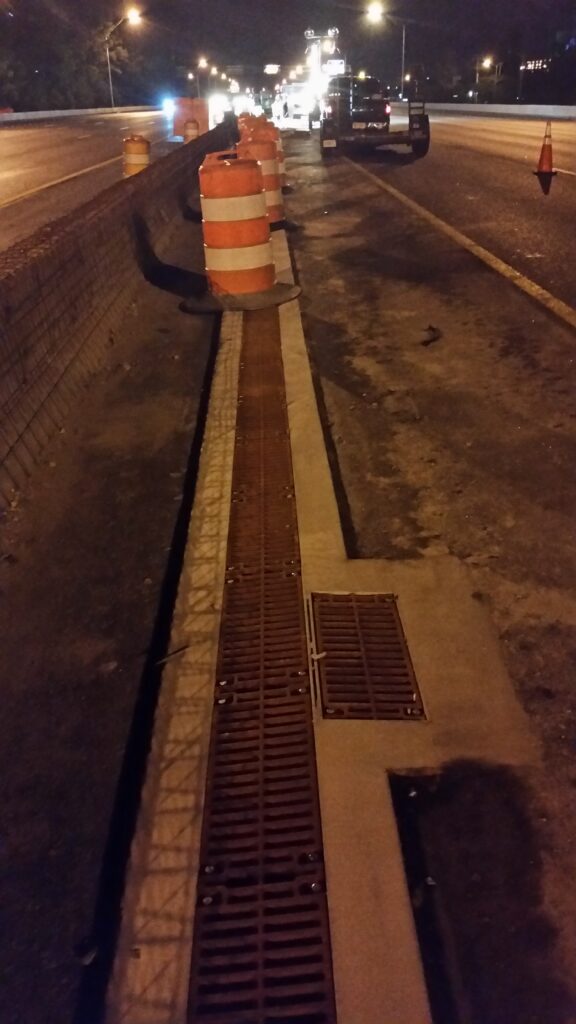
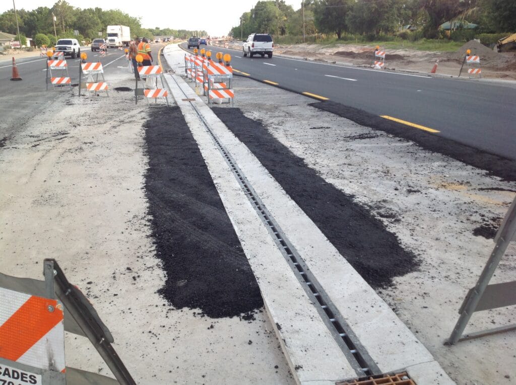
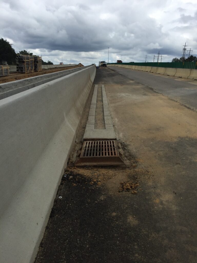
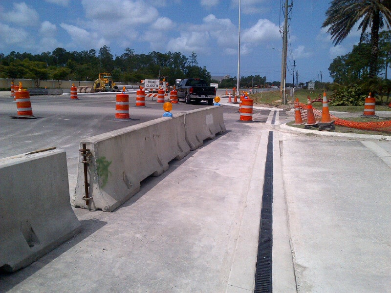
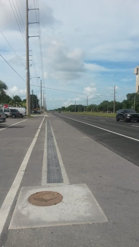
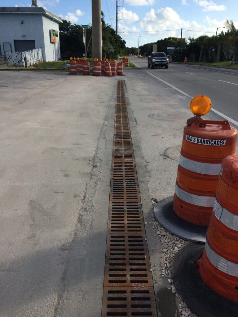
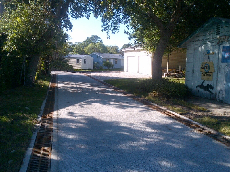
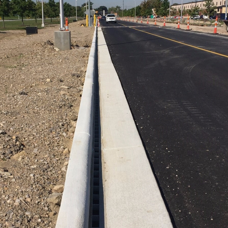
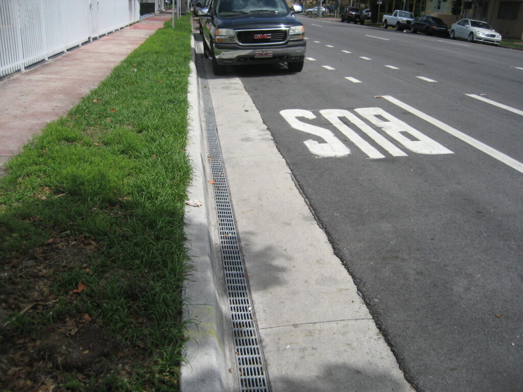
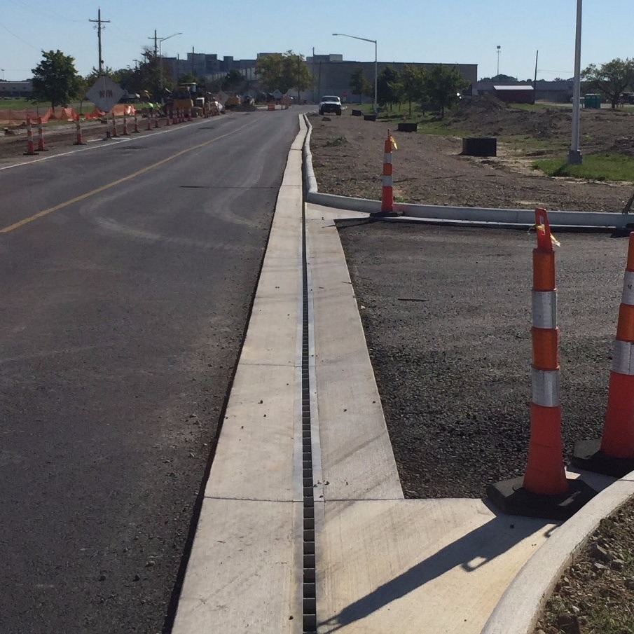
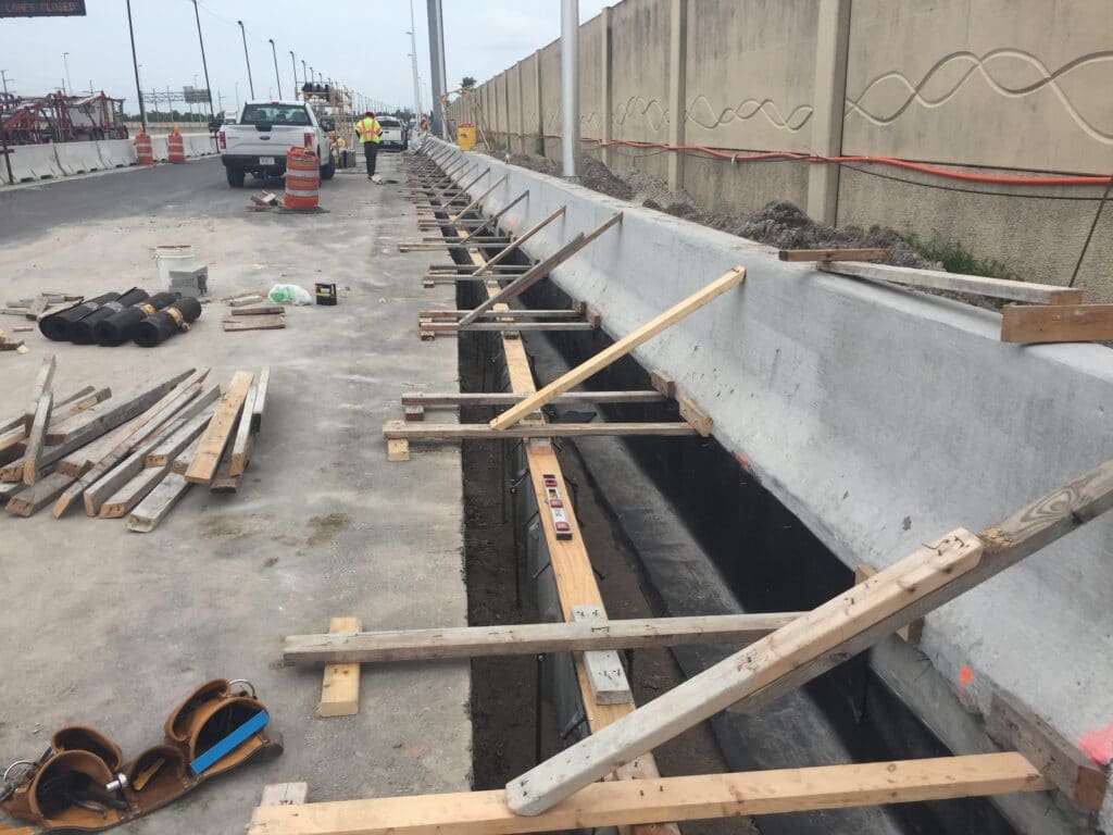
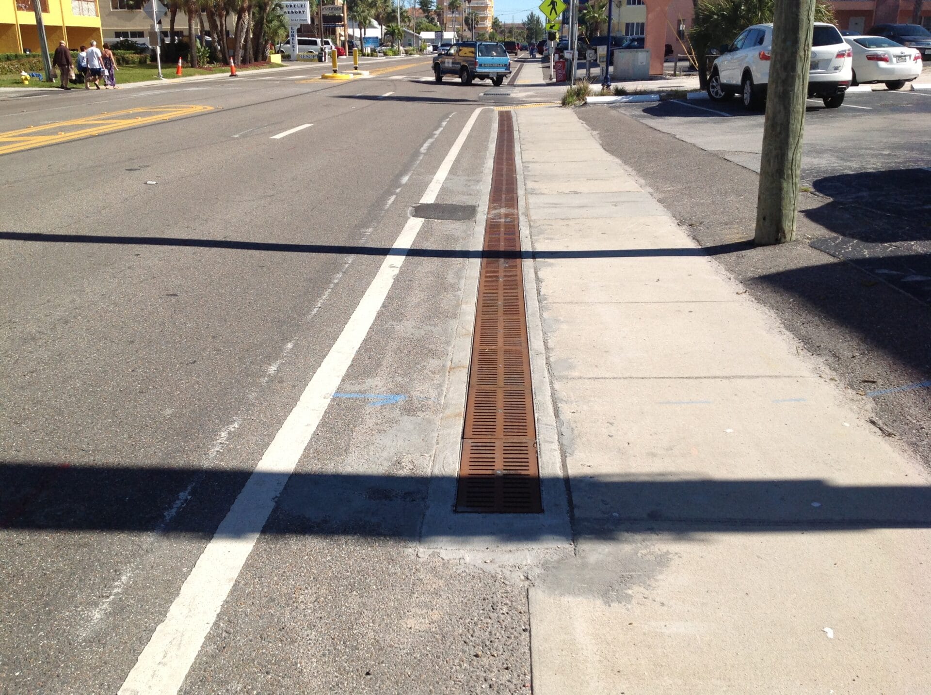
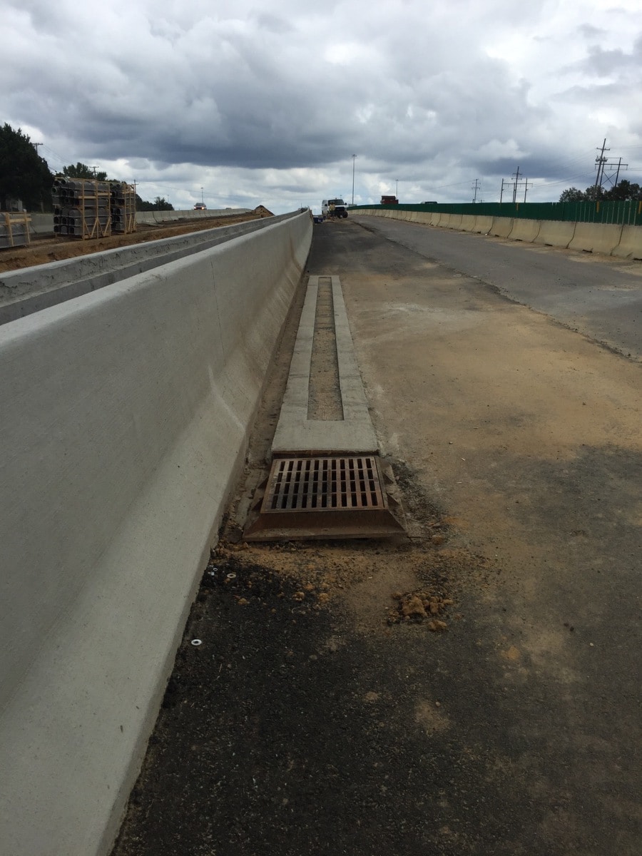
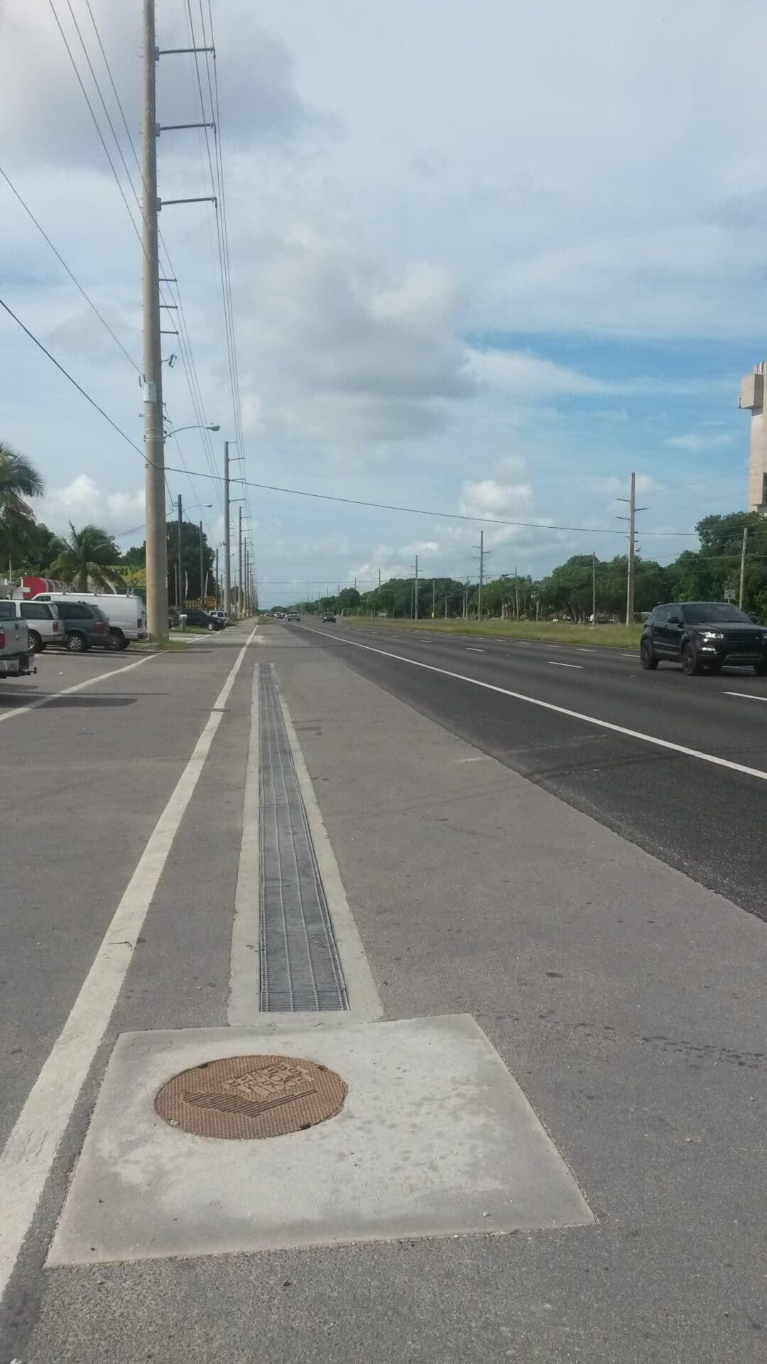
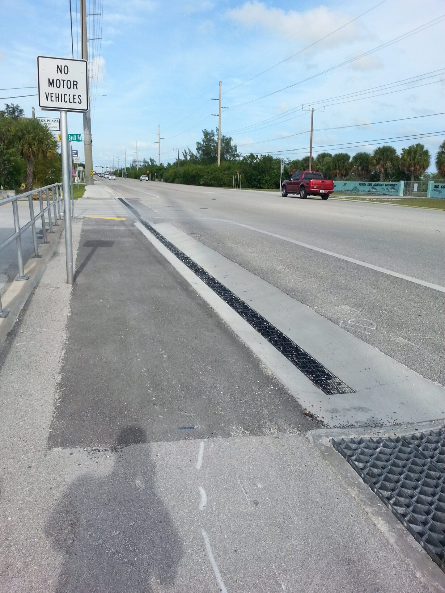
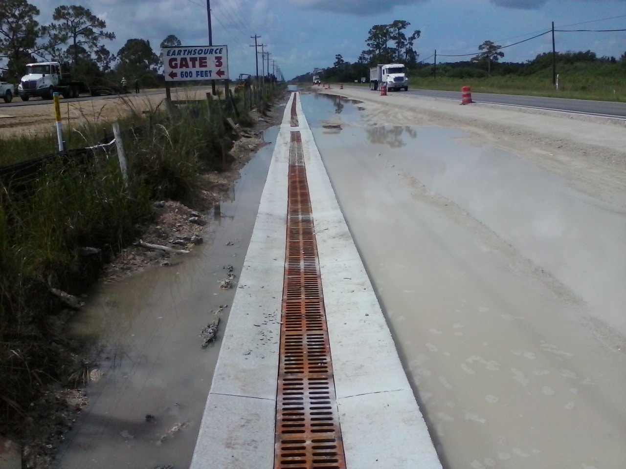
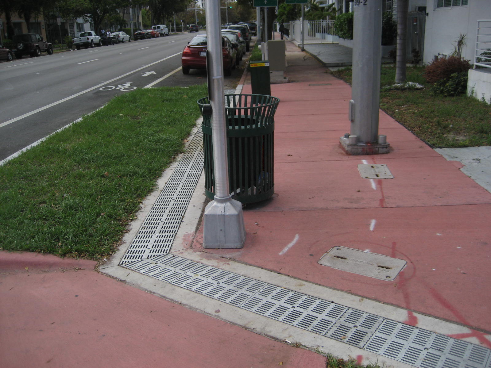
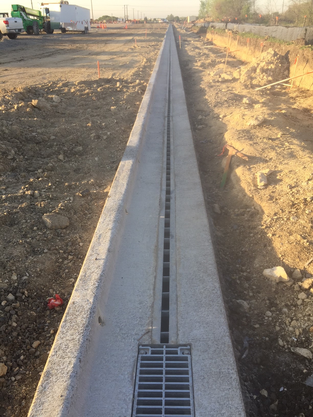
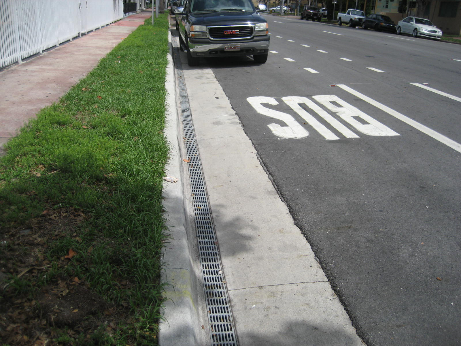
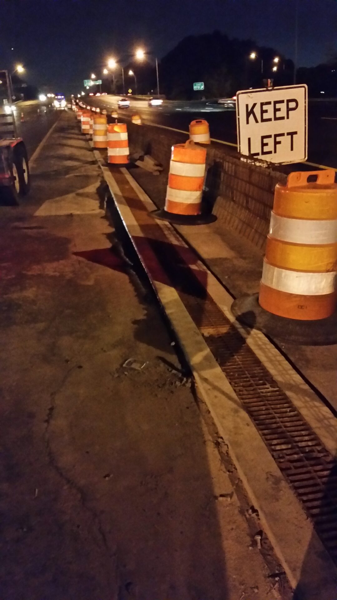
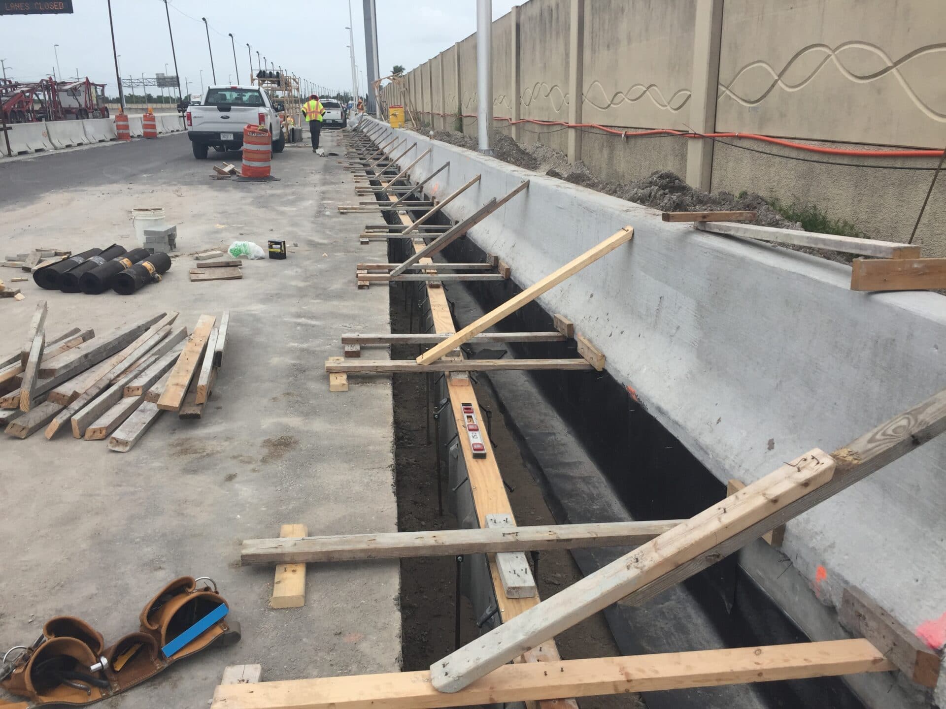
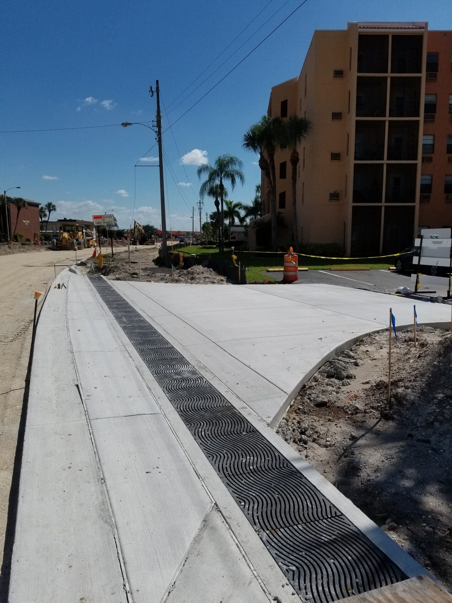
Roadway design breaks down into four basic categories; Restricted or triangular gutter flow, sheet flow, retrofit or repair work, or curb return applications. Triangular gutter flow applications are typically seen next to a barrier wall or in the gutter of a curbed section of roadway This design method is also used where a trench drain is placed in a valley. Sheet flow applications are often seen at driveway entrances, across streets without a crown, or access ramps on and off of limited access roadways. Retrofit or repair work is typically seen where an inlet did not get placed in the low point making a sloped trench drain system an easy fix. Curb return systems are placed in the radius of an intersection to keep wheelchair ramps dry and eliminate problems with complex grades associated with placing an inlet structure close to the radius of an intersection.
Roadway systems should meet all AASHTO H-20 load ratings and all AASHTO M309 ratings. There should be no flow restrictions inside the trench cross section to catch debris. Grates should be ductile iron. UV light and thermal degradation eliminate the use of any plastic components. Further information on Roadway design can be found at this paving contractors site.
Design Considerations
Sizing the drain
- The design capacity of the trench is determined by the amount of runoff that will be captured by the drain. The most common method for determining this is the Rational Method (Q=CIA where Q is the design flow)
- For constrained flow or valley flow you would use the equations for triangular gutter flow. For sheet flow there are a different set of simple calculations.
- In sheet flow applications you may need to size the drain up to catch the water in applications where there is a steep slope, otherwise, the size of the drain should closely follow the hydraulic requirements of the channel.
- Be sure that you add the site slope when calculating the size of the drain. The site slope will assist the trench increasing flow rates.
- For exterior applications where you will be handling storm water you should use the minimum size that you calculate using the cubic feet per second storm water calculations. Often we want to put free-board at the top of the drain to be conservative or design for a very large storm. This is not a good practice when it comes to trench drains. By doing this you not only cost yourself extra money but you keep flow rates inside the trench drain low which allows debris to build up. A radius bottom trench drain will help with this but it is best to design near actual capacity when possible.
- Be sure that the outlet capacity does not limit the flow of the drain. Outlet connections can be piped to structures or the trench can run directly into a structure. If piping to a structure make sure the pipe is sufficiently large (usually 8″ or 12″ is sufficient). If you are going directly into the structure use a full flow connector that turns the entire channel under the frame of the structure so as not to limit flow into the structure.
Choosing the channels
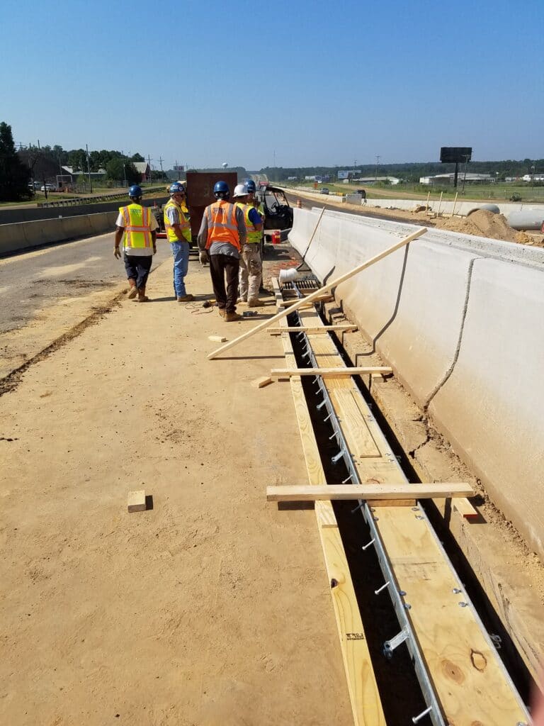
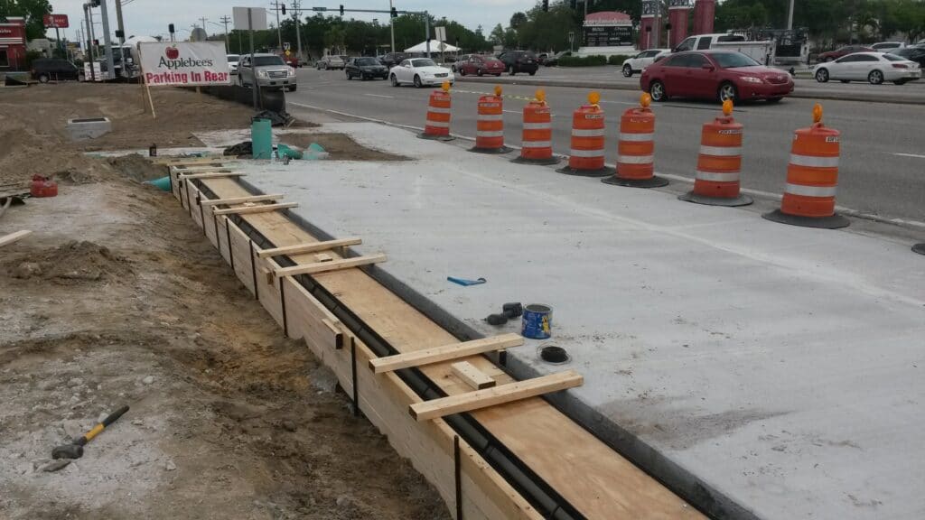
- Roadway applications are exterior applications and are therefore subject to thermal cycles and/or freeze thaw cycles, ultraviolet light, cyclic loading and often heavy traffic. The channel material should be composed of a material that expands and contracts at the same rate as the surrounding concrete. The channel material should not be affected by UV light. The channel material should not be between the frame of the system and the concrete unless the compressive strength of the material is at least as strong as the surrounding concrete. The material should be of sufficient thickness and strength to handle the constant cyclic loading that vehicle traffic subjects the system to. For this type of application there are often specialized systems avaliable. The best materials for the channel are precast fiberglass or concrete.
- In exterior applications you need to ensure that the drain will not degrade with exposure to ultraviolet light (UV light). It is a good idea to use a trench channel that has a radius bottom. The radius bottom will help with the accumulation of debris.
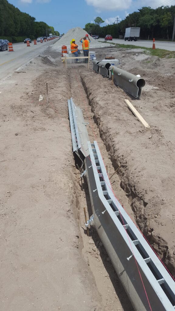
- Be aware of the dynamic loads that can be placed on these systems. Often turning or breaking on the trench grates can transfer severe loads through the grates into the channels. A rail or frame is essential on all roadway applications. The frames/rails need to be anchored at regular intervals. One of the most common system failures is lack of anchors on the rail/frames. The rail should have sufficient bearing area under it to support the entire load of the grate. Several studies have been done that show the bearing area under the grate to be one of the leading causes of trench drain failures.
- Sealing channel joints is typically not necessary. Some areas will require the joints to be sealed due to freeze thaw cycles but most states and municipalities are comfortable relying on proper vibration of the concrete to prevent water from getting in the trench joints. However, if you do want the joints sealed you must specify such and stress to the contractor that this be done properly. Polymer concrete and Fiberglass channels should be sealed with a urethane joint sealant. HDPE channels should be welded together with a continuous heat welding process because sealants do not stick to this material over time.
- Exterior applications or indoor applications that will not be temperature controlled will see severe changes in temperature and should have similar thermal coefficients of expansion to that of the surrounding concrete encasement. For more information see thermal expansion properties.
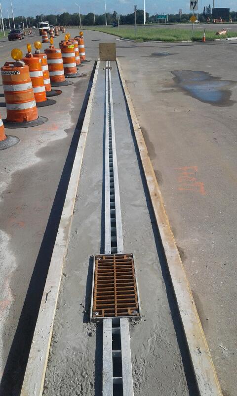
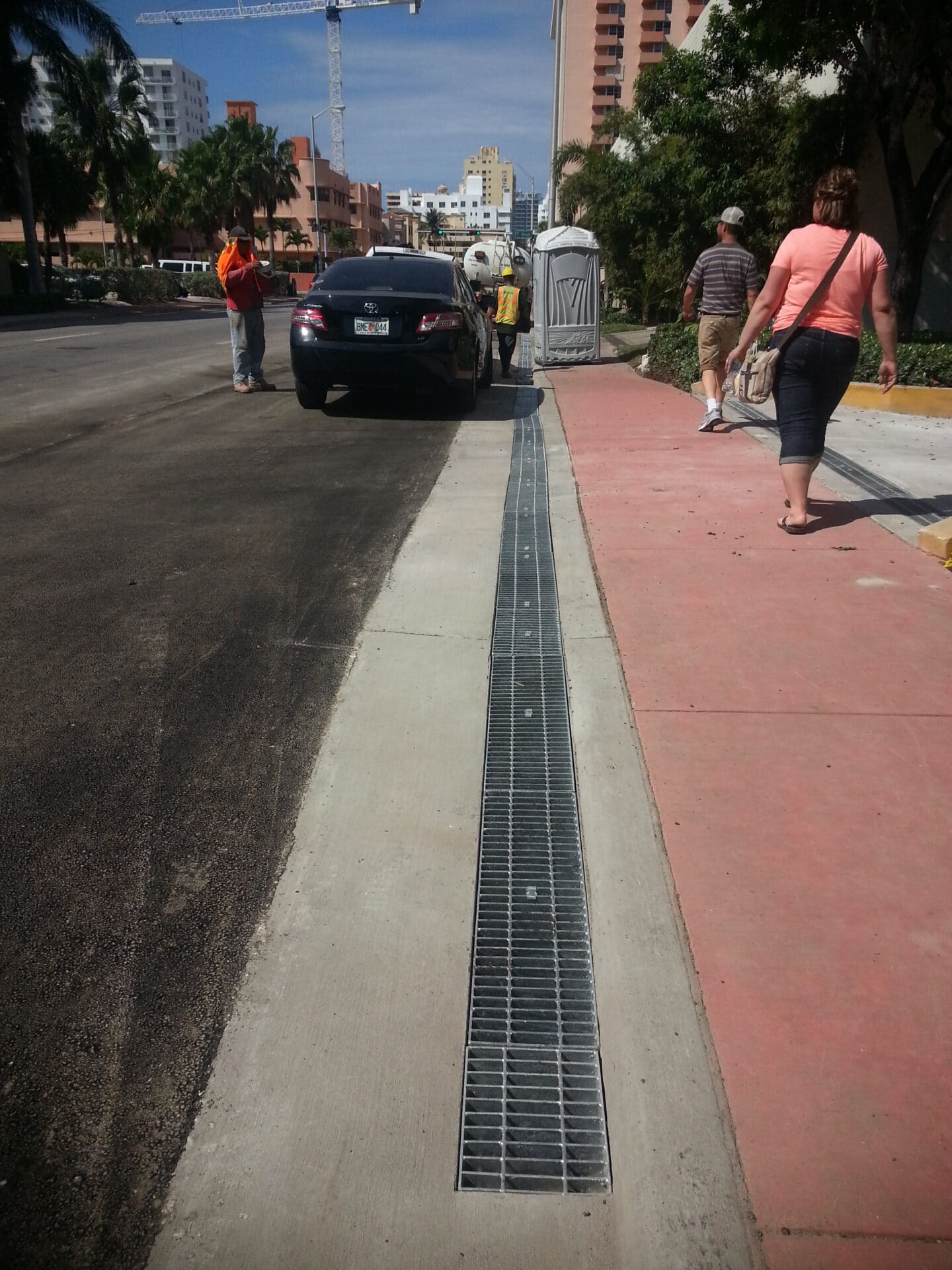
Selecting the grate material
- Grates for roadway applications should be ductile iron or cast iron. Cast iron grates are more susceptible to failure over time, however ductile iron grates cost a little more than cast iron. The other huge advantage of choosing ductile iron is that the strength to weight ration is much greater. What this means is that for the same strength grate you can have more open area. This is important with the amount of debris that is present on the roads. The more open area and the larger the geometry of the openings the less likely the grate is to plug and not work properly.
- Make sure that the openings on the grate are as large as possible to ensure that clogging is not a factor. Clogged grates can cause roadway ponding and be a real safety hazard. In roadway traffic there should be little if any pedestrian traffic. The smaller the openings the more frequent cleaning of the grates will be necessary. The larger the openings, the more likely the debris is to flush through the system.
- Be sure the grates are properly anchored. The best is to use a system that locks all four corners into the concrete. Anchoring grates using toggles is not a wise choice if it is in a regular traffic lane. Toggles are acceptable for use in curb and gutter or other occasional traffic areas. Be sure that any removable grates are anchored into place with galvanized or stainless steel anchors. If you use a plastic anchor it will degrade over time.
Designing the layout
- Trench drain runs along a barrier wall or in curb and gutter can be lengthy runs due to the flat longitudinal slope that is often present. Due to the long runs be aware of the depths of the trench drain systems. Use systems that can handle the long runs or choose to have multiple outlets.
- The depth of the system that you are going to use can conflict with piping and other buried utilities.
- Outlets should be placed to minimize piping, but try to avoid making the outlets further apart than the standard run length (Dura Trench can run hundreds of linear feet but the depth of the system will be the limiting factor for where you should place outlets) of the trench drain system that you have chosen. If the run length exceeds the standard run length multiple outlets, neutral (non-sloping) channels or sidewall extensions must be used. If you use neutral (non-sloping) channels be aware of what it does to the flow capacity of the system. Neutral channel sections can also cause debris to settle out of the system and increase maintenance cycles of the trench drain.


