Mannings Equation
For most projects, it is sufficient to utilize Manning’s equation for open channel flow to determine the trench capacity (i.e., required flow and size). You must first calculate the flow rate to be captured by the channel drain system. For indoor applications, this is generally determined by the process equipment flow rates, wash-down hoses, dumping containers, etc. For exterior applications, it is dependent on the rainfall of the area.
Exterior applications are generally calculated by using this formula: Qr = C*I*A
Where as …
C is a constant that relates to the surface the drain is installed in (ex., for rigid pavement use 0.9)
I is the rainfall intensity of the design storm (ex., in the south, this can be as much as 8 or 9 inches per hour, in the northern united states, it is closer to 4 or 5 inches per hour)
A is the drainage area in acres (ex., take the length in feet times the width in feet and then divide by 43560 to convert square feet into acres)
When you multiply these factors together, you get the design flowrate (Qr = Q required) of the drain in CFS (cubic feet per second)
**Note: There are other methods of calculating design flows, and these calculations are intended to get you in the ballpark. Consult a licensed civil engineer for expert advice in applications requiring more accurate measures.
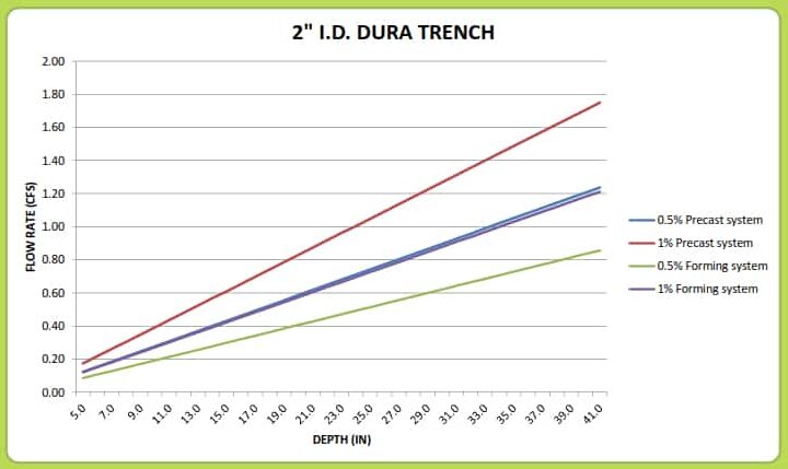
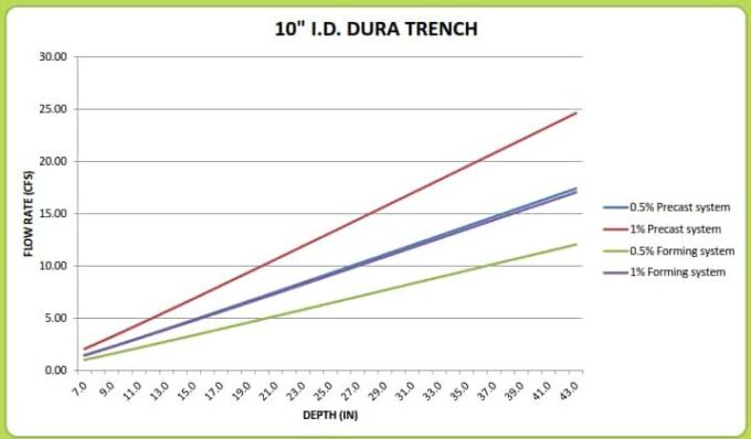
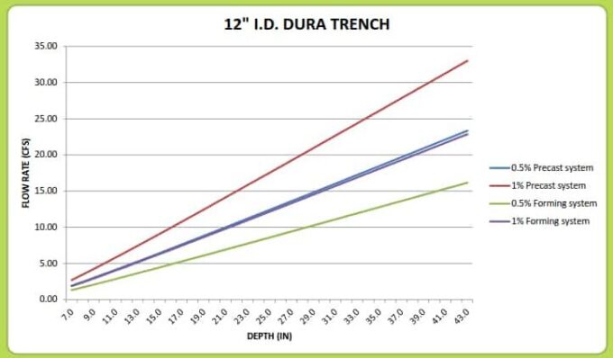
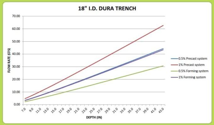
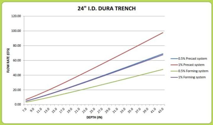
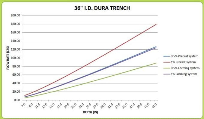
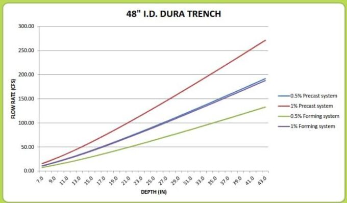
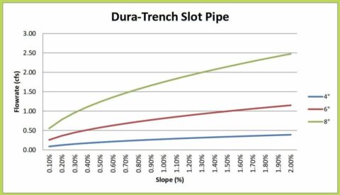
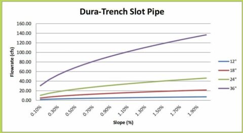
Now it is time to calculate the channel flow capacity to determine what size trench may be required for your application by using this formula: Qc = A*(1.49/n)*(R)^2/3*(S)^1/2
Where as…
A is the cross-sectional area of the trench drain in square feet
n is the coefficient of friction of the trench drain body (concrete forming systems = 0.013, polymer concrete systems 0.010, fiberglass & GFRPC systems 0.009)
R is the hydraulic radius which is calculated by A / P where A is the cross-sectional area found above, and P is the perimeter surface of the trench
S is the slope of the bottom of the trench (be sure to add the site slope and the built-in slope of the trench drain system together to get the total effective slope – ex. site slope is 0.5%, and the trench slope is 1%; therefore, the total slope is 1.5% or 0.015)
For help with sizing the trench, please contact our engineering department; they will gladly help you with your application.