
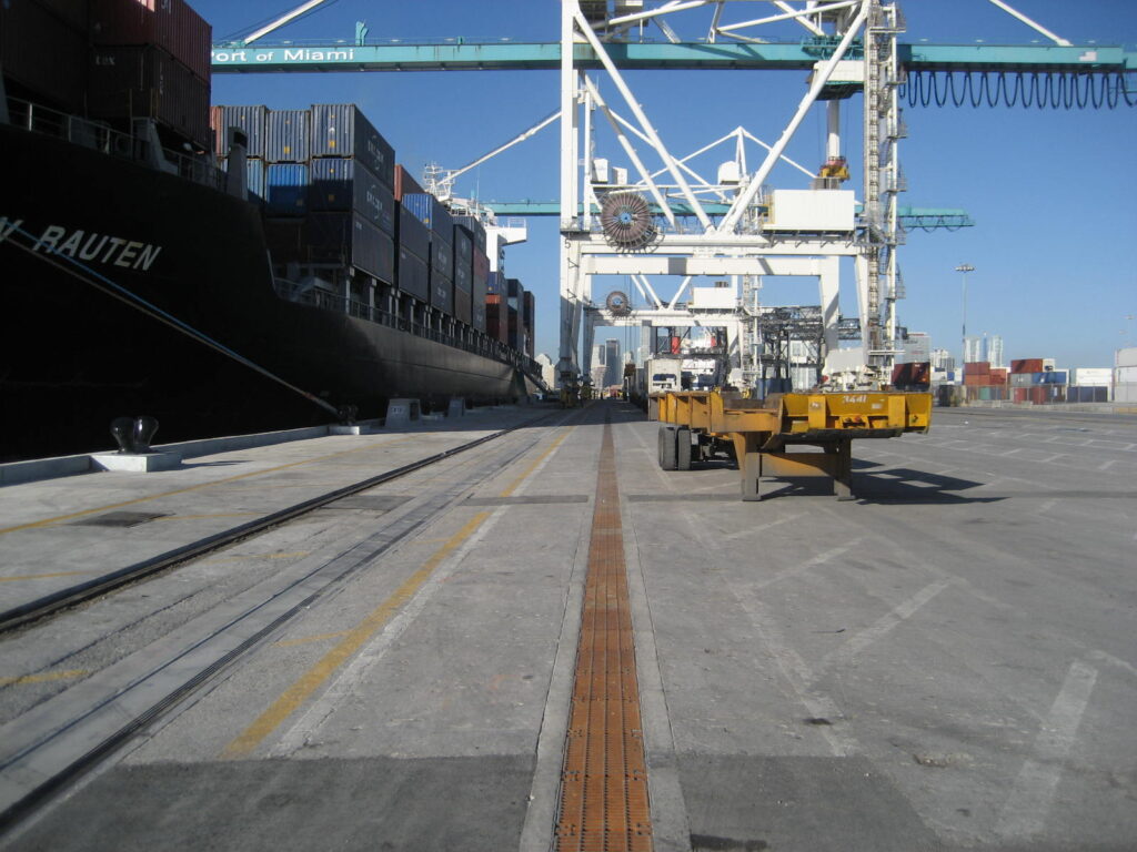
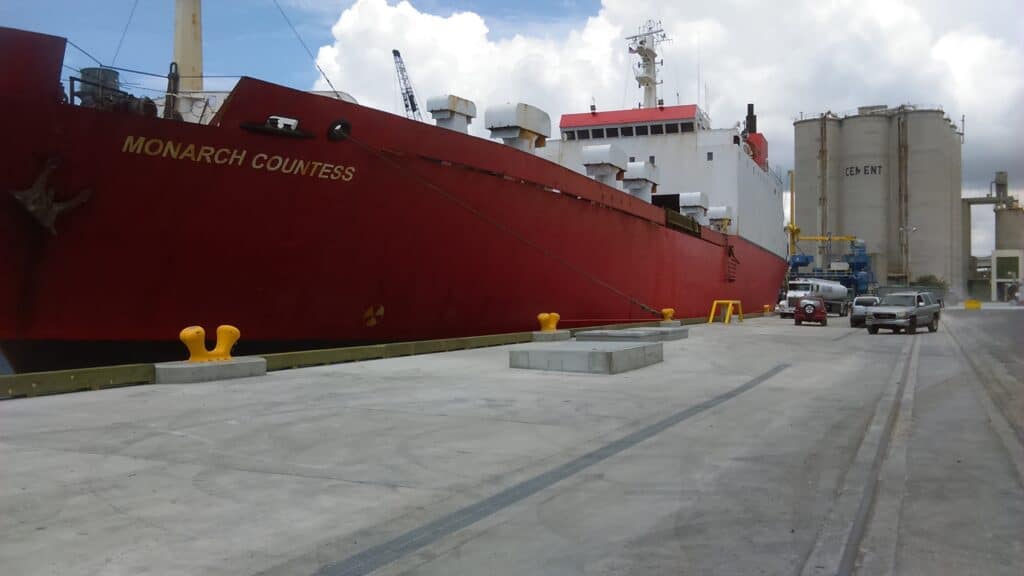
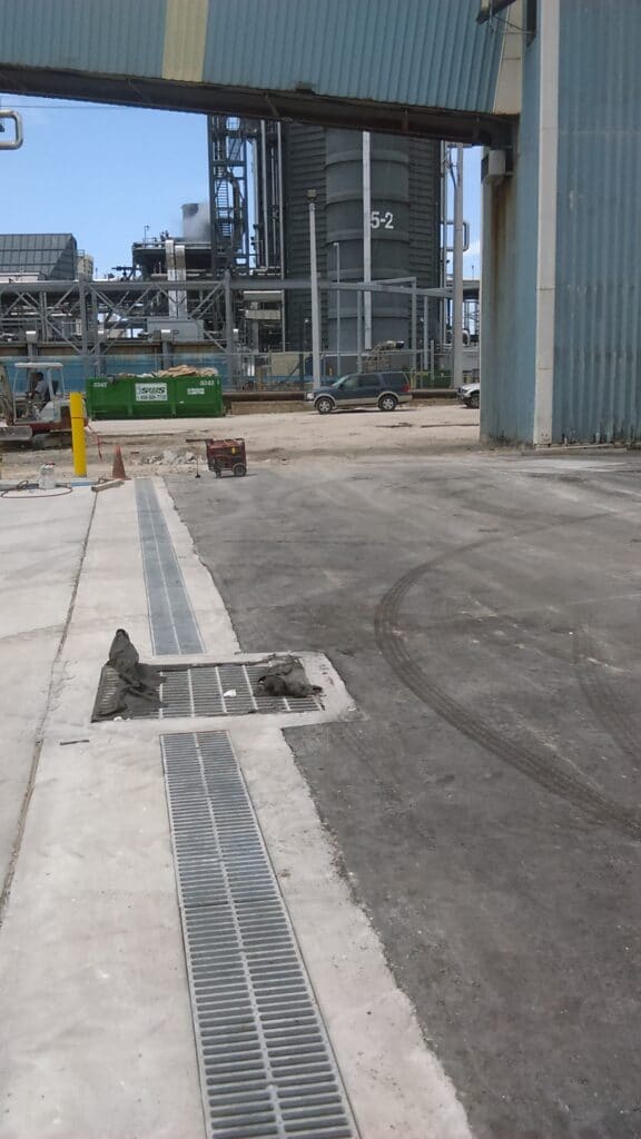
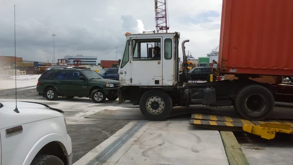
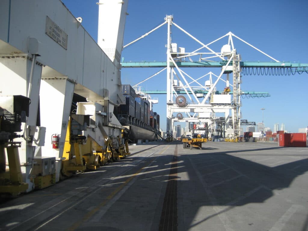
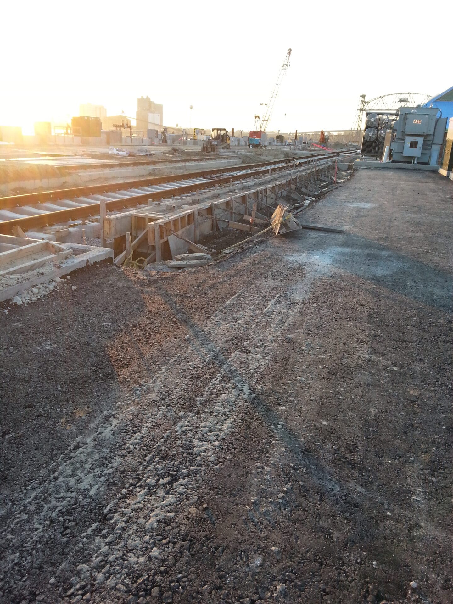
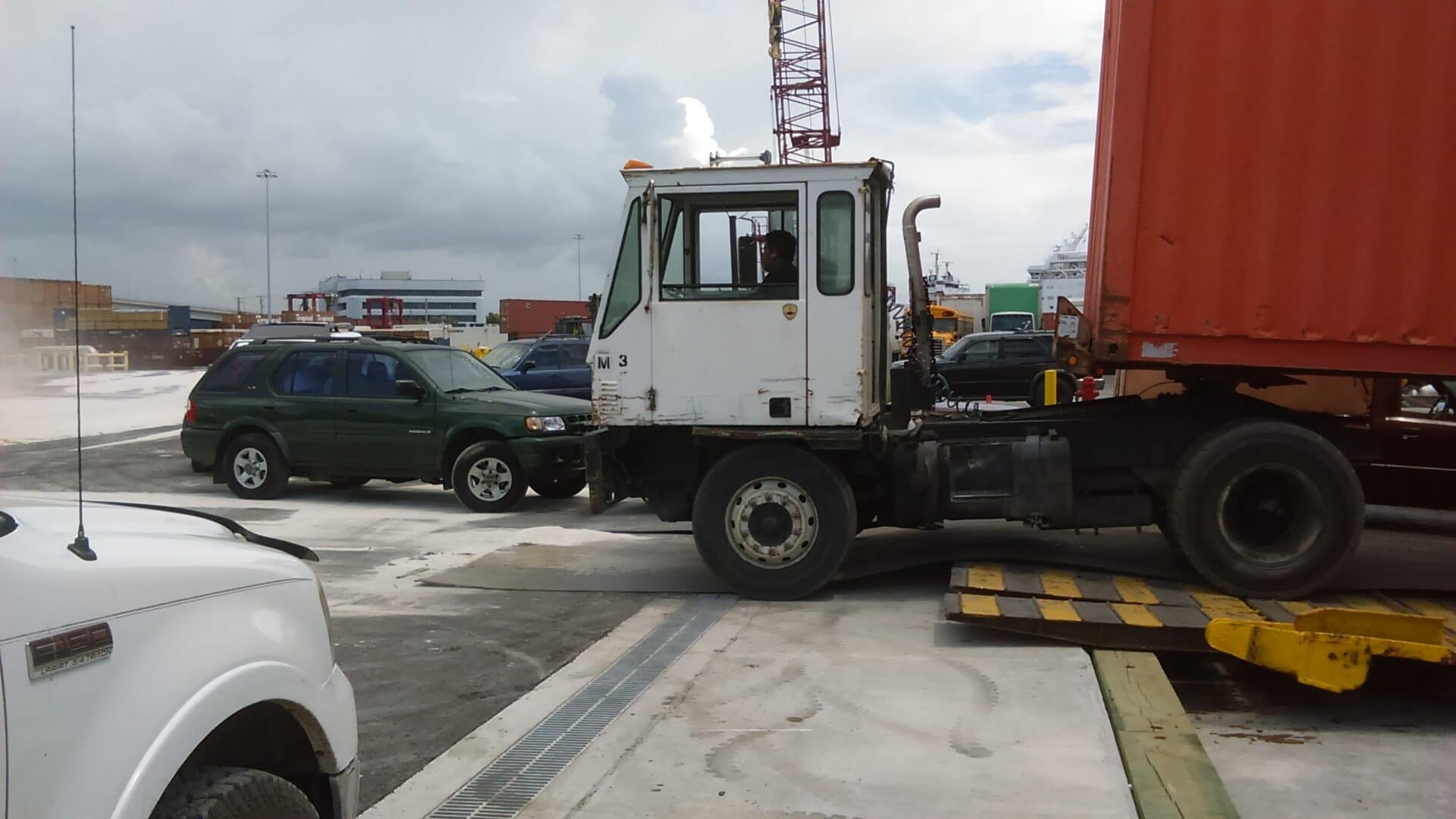
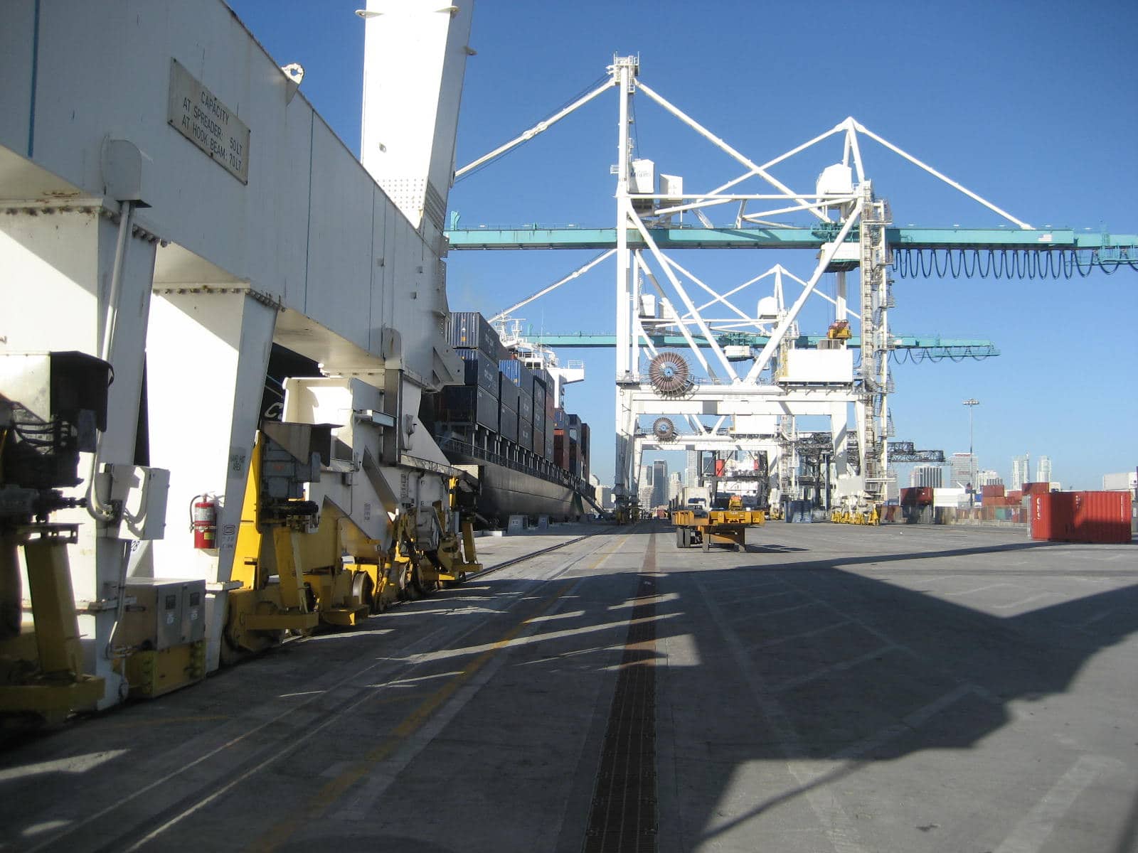
Sea ports and intermodal transportation yards have been subject to increasing environmental regulation. Trench drains and slot pipes are being used to capture and treat the storm water before releasing it off the site. A trench drain or slot pipe are typically chosen due to the need for simple slopes and long flat sites. The constant traffic of trucks and large forklifts makes this one of the most brutal linear drain applications. If a proper trench drain or slot drain is selected, the concrete around the trench will often fail before the drain itself.
Trench Drains and Slot Pipe for Sea Ports & Intermodal Facilities


Design Considerations
Sizing the Drain
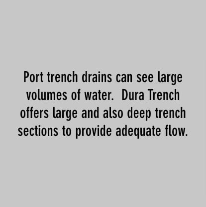
- The size of the drain will be determined by the amount of water being captured, where the outlets can be located, and the debris capturing ability. The further apart the outlets are the larger the drain may have to be to convey the storm water. In bulk unloading areas the drain may be larger to contain spilled materials and allow excavation equipment to clean the trenches.
- In most storm water only cases an 8″, 10″, or 12″ wide internal trench drain is used. Minimal widths are desirable in order to keep the span on the grating to a minimum and keep cost down. Larger widths are often used more for bulk unloading areas where large spills could occur that may need to be cleaned out of the trench with a piece of equipment.
- The slope of the drain can be adjusted to decrease the size of the drain if the outlet pipes are spaced close enough to allow for this without getting into the water table.
Choosing the channels
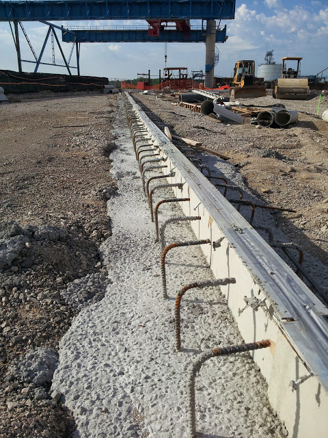
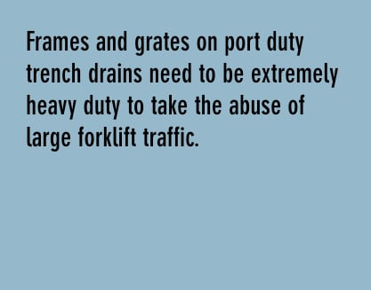
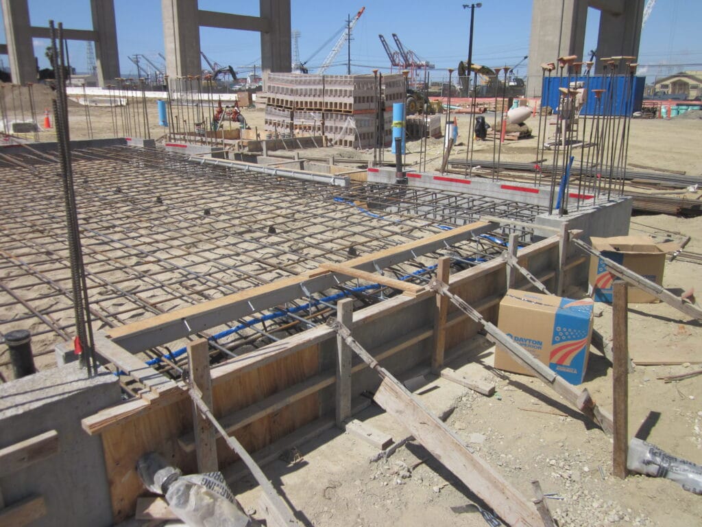
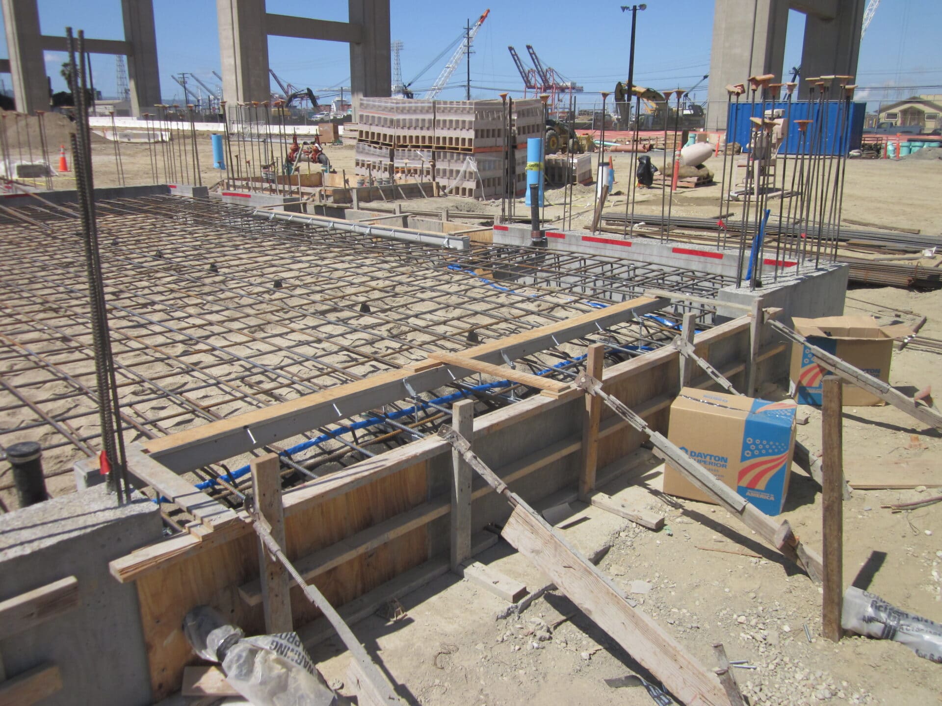
- The channel must have the largest frame possible to carry the extreme loads in these applications. The frame should not exert load on any prefabricated channel component. The extreme loads will crush any prefabricated channel if it bears directly on the channel. All loads should be surrounded to the surrounding concrete.
- Frames should have long sections and very large bearing surfaces to properly transfer the loads. The frame assemblies should have large concrete anchors spaced at short intervals, or the frame should be tied directly into the structural reinforcing cage to eliminate any torques that may be exerted on the frame.
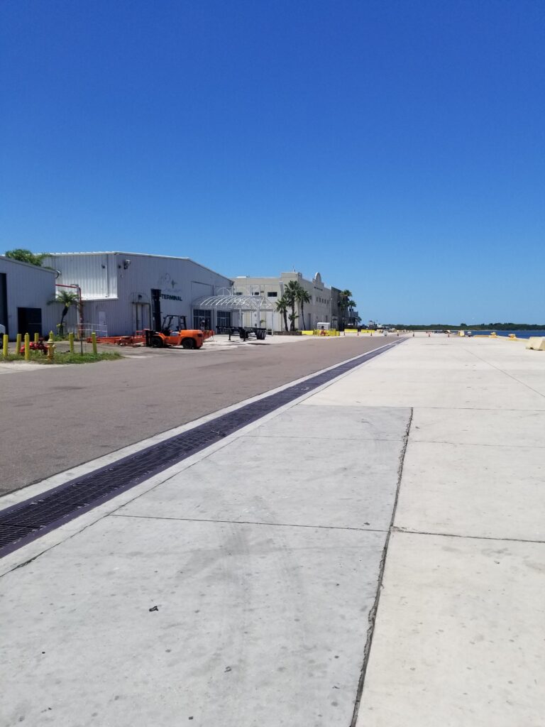
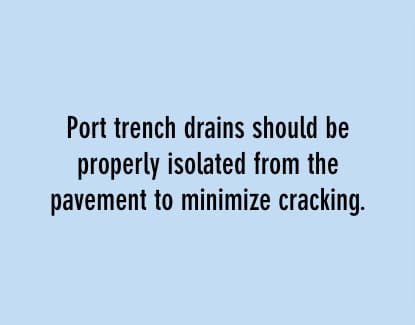
- Smooth precast channels such as GFRPC will carry more flow than a cast in place trench and can help keep depths to a minimum. In most applications this will save a lot of cost on both the product and installation. A high strength concrete mix design and proper concrete consolidation with a pencil vibrator is highly recommended. The trench drain system will last as long as the concrete surround is in good condition.
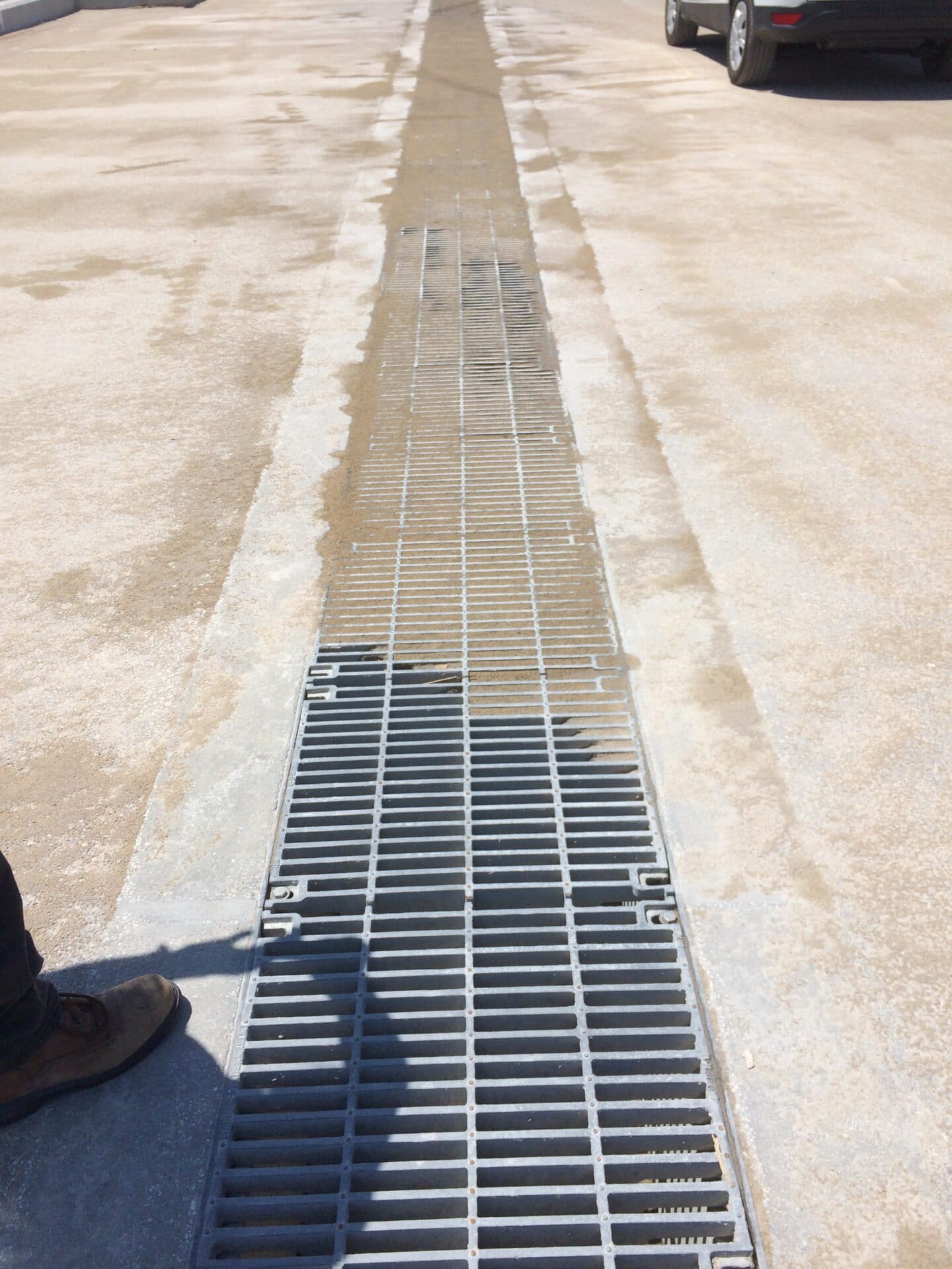
Selecting the grate
- The grates should be ductile iron or galvanized steel. The salt water environment is not good for other materials.
- The grates should be load tested to exceed the loads exerted with a minimum of a 2:1 safety factor. Typically grates rated for DIN load class E or F are used.
- Grates are typically bolted down with large diameter fasteners to ensure that they do not come out of the trench. High speed traffic turning or breaking on the trench drains can cause the grates to come out and cause a dangerous situation if not properly secured to the trench drain frame.
- Larger systems that may handle bulk solids are not locked down in some cases due to the increased weight of larger trench drain grates.
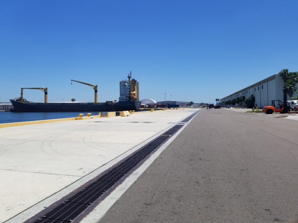
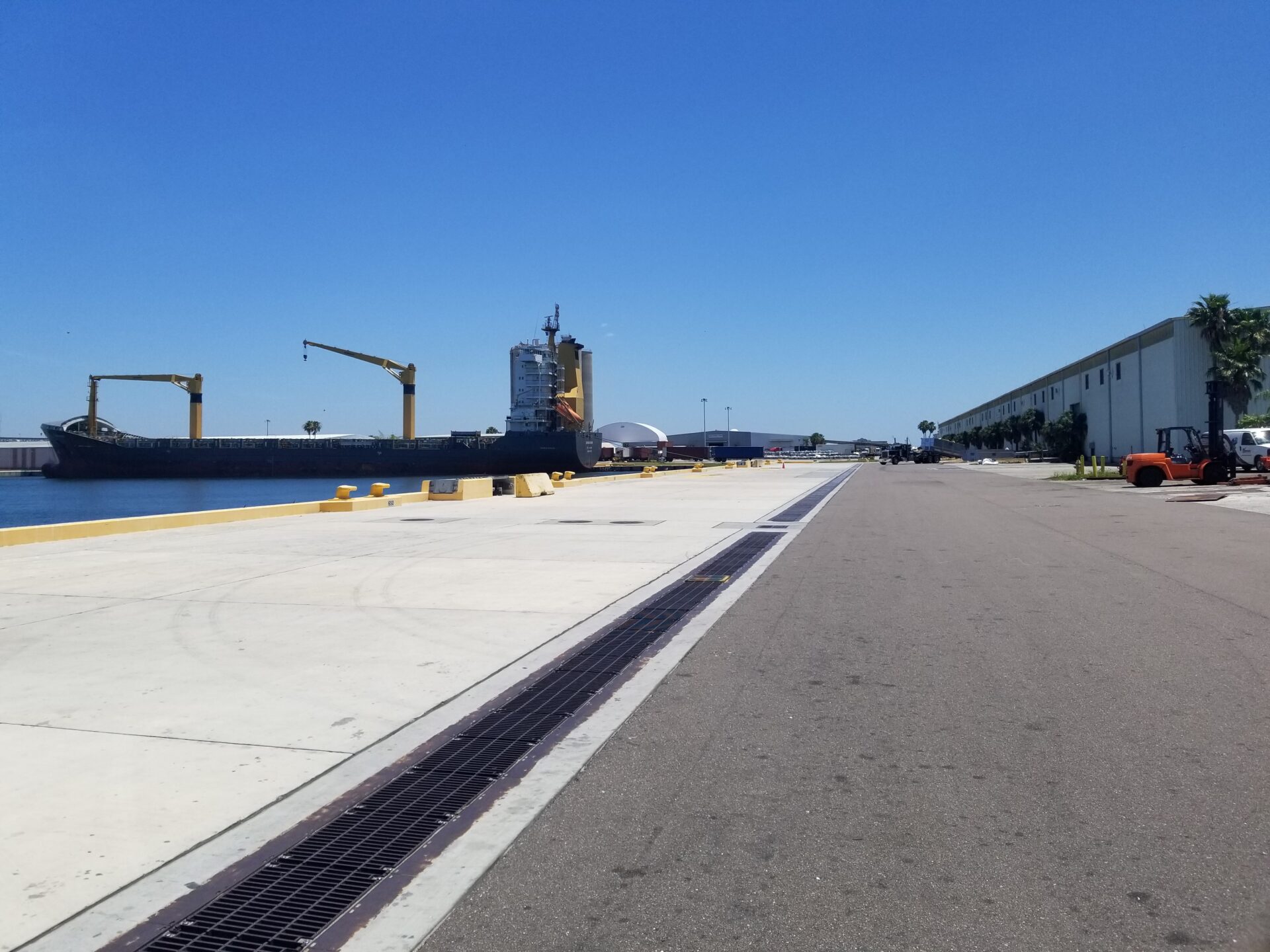
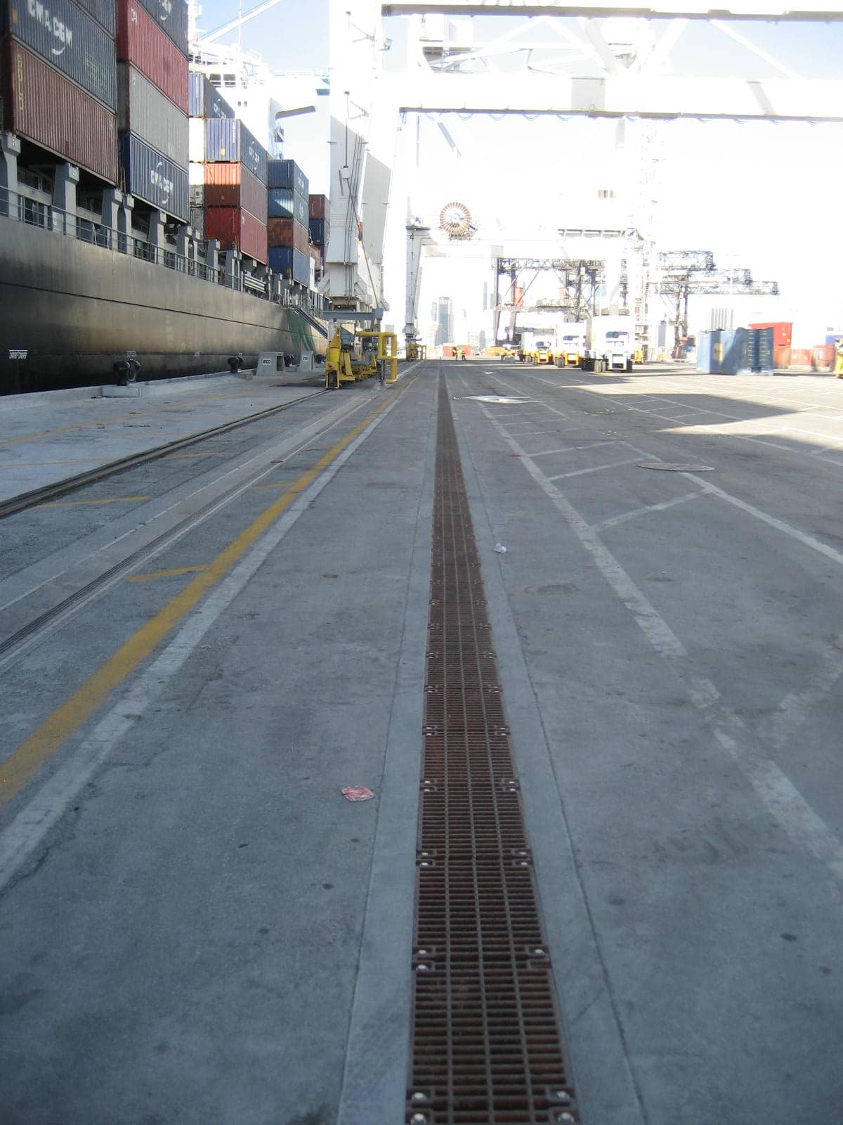
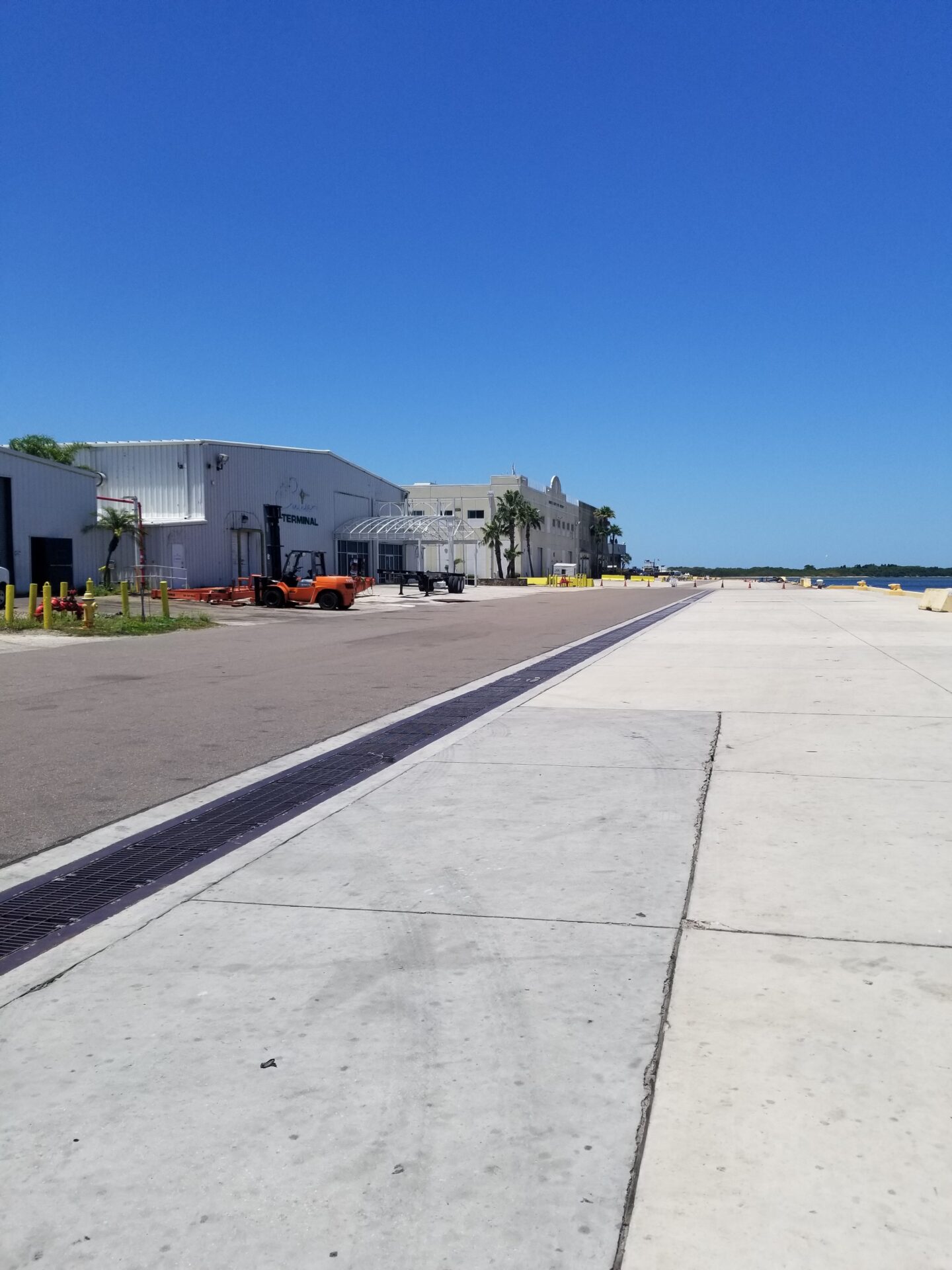
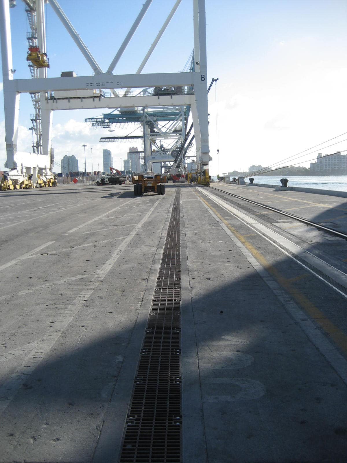
Designing the layout
- The typical layout for a port or inter modal application is a long straight run with multiple in line structures tying to the storm water piping system. The distance between the pipes is usually between 300 and 500 feet, but can vary with site conditions.
- Where possible try to keep the slopes at 0.25% minimum to ensure proper grit and debris flushing.